Home
/ Astable 555 Timer Schematic : File 555 Astable Diagram Svg Wikimedia Commons - Astable multivibrator is also called as free running multivibrator.
Astable 555 Timer Schematic : File 555 Astable Diagram Svg Wikimedia Commons - Astable multivibrator is also called as free running multivibrator.
Astable 555 Timer Schematic : File 555 Astable Diagram Svg Wikimedia Commons - Astable multivibrator is also called as free running multivibrator.. This attributes the circuit with the property. We often use astable multivibrator mode. That it for a astable 555 timer mode! If you still need a detailed understanding of the 555 timer. Derivatives provide two (556) or four (558) timing circuits in one package.
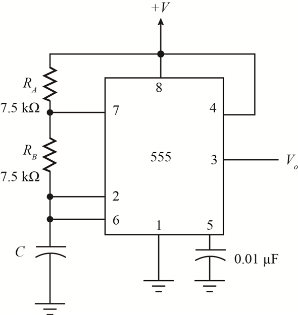
Circuit with internal block diagram. Since the control voltage (pin 5) is not used the comparator reference voltages will be 2/3 vcc and 1/3 vcc respectively. It was designed in 1970 and introduced in 1971 by signetics (later acquired by philips). The 555 has three main operating modes, monostable, astable, and bistable. 555 timer astable multivibrator circuit diagram.
Solved Chapter 13 Problem 14p Solution Electronic Devices And Circuit Theory 11th Edition Chegg Com from media.cheggcdn.com See in the circuit diagram is standard 555 circuit. It has no stable states and continuously the schematic of the pulse position modulator using two 555 timer ic's is shown below. The 555 timer is a chip that can be us… Derivatives provide two (556) or four (558) timing circuits in one package. The 555 timer is an integrated circuit, it is extremely versatile and can be used to build lots of different circuits. Let's take a closer look what's inside the 555 timer and explain how it works in each of the three modes. Astable multivibrator using 555 timer block diagram. In this article, we will cover about 555 timers.
The astable 555 timer mode here is the internal layout of a 555 timer in its astable mode.
Look at the circuit diagram. Astable multivibrator using 555 timer block diagram. We often use astable multivibrator mode. Since the control voltage (pin 5) is not used the comparator reference voltages will be 2/3 vcc and 1/3 vcc respectively. So the output of the 555 will set (goes high) when the capacitor voltage goes below 1/3. Astable mode of 555 timer. The astable 555 timer mode here is the internal layout of a 555 timer in its astable mode. 555_timer1.cir download the spice file. You may not be able to see a clear picture of the 555 timer runs. The 555 timer ic is an integral part of electronics projects. It has no stable states and continuously the schematic of the pulse position modulator using two 555 timer ic's is shown below. Thank you for watching (reading) the episode! This attributes the circuit with the property.
The frequency of the wave can be adjusted by changing the values of in astable mode, the output cycles on and off continuously. Now the schematic symbol and pcb symbol are created for the 555 timer. The 555 timer connections as astable multivibrator and it's operation let's see how the 555 timer astable multivibrator connections are made in the circuit diagram. Derivatives provide two (556) or four (558) timing circuits in one package. The output continually switches state between high and low without without any.
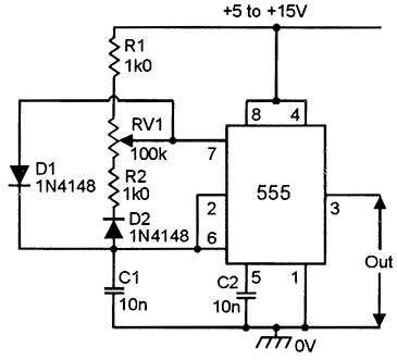
555 Astable Circuits Nuts Volts Magazine from www.nutsvolts.com The 555 timer changes its output depending on the state of two inputs. (1) for all available packages, see the orderable addendum at the end of the datasheet. [node:summary555 timer ic is one of the commonly used ic among students and hobbyists. Astable mode of 555 timer. This attributes the circuit with the property. To end the simulation, click on the stop button. The duty cycle is set by a potentiometer, p1. Thank you for watching (reading) the episode!
Due to its relative simplicity, ease of use and low cost it has been used in literally thousands of applications and is still widely available.
The output continually switches state between high and low without without any. See in the circuit diagram is standard 555 circuit. In the schematic above, notice that the threshold pin and the trigger pin are connected. The scope shows the resultant output from the 555 timer. Now the schematic symbol and pcb symbol are created for the 555 timer. Each mode represents a different type of circuit that has a particular output. The 555 timer ic is an integral part of electronics projects. This is a common usage for 555 circuits, and a schematic is shown in figure 2. Astable multivibrator mode of 555 timer ic. 5.29 shows a 555 timer configured as an astable or multistable multivibrator 66. In this case, the fixed value of the capacitor is 100uf. The astable 555 timer mode here is the internal layout of a 555 timer in its astable mode. The 555 timer connections as astable multivibrator and it's operation let's see how the 555 timer astable multivibrator connections are made in the circuit diagram.
In astable mode, the 555 timer acts as an oscillator that generates a square wave. Astable multivibrator is also called as free running multivibrator. Circuit with internal block diagram. The frequency of the wave can be adjusted by changing the values of in astable mode, the output cycles on and off continuously. It was designed in 1970 and introduced in 1971 by signetics (later acquired by philips).
555 Timer 8 Steps With Pictures Instructables from content.instructables.com There are a lot of applications of this ic, mostly used as vibrators like, astable multivibrator, monostable multivibrator, and bistable multivibrator. Look at the circuit diagram. If you still need a detailed understanding of the 555 timer. The 555 timer was introduced over 40 years ago. Bringing your attention to wiring through pins 2 and 6 (yellow wire). (1) for all available packages, see the orderable addendum at the end of the datasheet. [node:summary555 timer ic is one of the commonly used ic among students and hobbyists. This tutorial provides sample circuits to set up a 555 timer in monostable, astable, and bistable modes as well as an in depth discussion of how the 555 timer works and how to choose components to use with it.
Since the control voltage (pin 5) is not used the comparator reference voltages will be 2/3 vcc and 1/3 vcc respectively.
This tutorial provides sample circuits to set up a 555 timer in monostable, astable, and bistable modes as well as an in depth discussion of how the 555 timer works and how to choose components to use with it. Outputs an oscillating pulse signal. The scope shows the resultant output from the 555 timer. 5.29 shows a 555 timer configured as an astable or multistable multivibrator 66. The threshold voltage for the first ic 555, which is. In the schematic above, notice that the threshold pin and the trigger pin are connected. The 555 timers name comes from the fact that there are three 5kω resistors connected together internally producing a voltage divider network the most common use of the 555 timer oscillator is as a simple astable oscillator by connecting two resistors and a capacitor across its terminals to. Look at the circuit diagram. 555 timer astable multivibrator circuit diagram. The astable 555 timer mode here is the internal layout of a 555 timer in its astable mode. Due to its relative simplicity, ease of use and low cost it has been used in literally thousands of applications and is still widely available. That it for a astable 555 timer mode! Since the control voltage (pin 5) is not used the comparator reference voltages will be 2/3 vcc and 1/3 vcc respectively.
The 555 timers name comes from the fact that there are three 5kω resistors connected together internally producing a voltage divider network the most common use of the 555 timer oscillator is as a simple astable oscillator by connecting two resistors and a capacitor across its terminals to 555 timer schematic. In this article, we will cover about 555 timers.
